lvpengwei’s Blog

学习历程,生活点滴。

Tgfx 实现 Blend

| Comments

问题

PAG 文件里的混合模式是从 AE 中导出的,然后使用 skia 内置的混合模式去实现,去掉 skia 之后,需要用原生的 OpenGL 来实现。

思路

既然 skia 内置的混合模式可以满足需求,那我们用 OpenGL 实现 skia 支持的就好,先看一下 skia 里面都有哪些混合模式。

1
2
3
4
5
6
7
8
9
10
11
12
13
14
15
16
17
18
19
20
21
22
23
24
25
26
27
28
29
30
31
32
33
34
enum class SkBlendMode {
  kClear, //!< replaces destination with zero: fully transparent  
  kSrc, //!< replaces destination  
  kDst, //!< preserves destination  
  kSrcOver, //!< source over destination  
  kDstOver, //!< destination over source  
  kSrcIn, //!< source trimmed inside destination  
  kDstIn, //!< destination trimmed by source  
  kSrcOut, //!< source trimmed outside destination  
  kDstOut, //!< destination trimmed outside source  
  kSrcATop, //!< source inside destination blended with destination  
  kDstATop, //!< destination inside source blended with source  
  kXor, //!< each of source and destination trimmed outside the other  
  kPlus, //!< sum of colors  
  kModulate, //!< product of premultiplied colors; darkens destination  
  kScreen, //!< multiply inverse of pixels, inverting result; brightens destination  
  kLastCoeffMode = kScreen, //!< last porter duff blend mode  
  kOverlay, //!< multiply or screen, depending on destination  
  kDarken, //!< darker of source and destination  
  kLighten, //!< lighter of source and destination  
  kColorDodge, //!< brighten destination to reflect source  
  kColorBurn, //!< darken destination to reflect source  
  kHardLight, //!< multiply or screen, depending on source  
  kSoftLight, //!< lighten or darken, depending on source  
  kDifference, //!< subtract darker from lighter with higher contrast  
  kExclusion, //!< subtract darker from lighter with lower contrast  
  kMultiply, //!< multiply source with destination, darkening image  
  kLastSeparableMode = kMultiply, //!< last blend mode operating separately on components  
  kHue, //!< hue of source with saturation and luminosity of destination  
  kSaturation, //!< saturation of source with hue and luminosity of destination  
  kColor, //!< hue and saturation of source with luminosity of destination  
  kLuminosity, //!< luminosity of source with hue and saturation of destination  
  kLastMode = kLuminosity, //!< last valid value  
};

blend mode

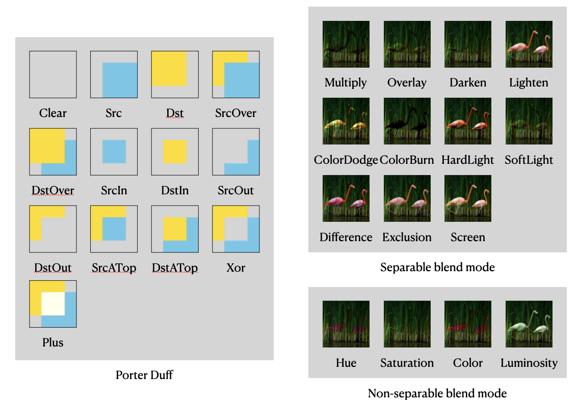
从实现方案上来说,这些混合模式都可以用 shader 来完成。其中kLastCoeffMode以上的混合模式也叫 PorterDuff 混合模式,它们还可以用 OpenGL 提供的 glBlendFunc来实现 。

解决

coeff blend mode

kLastCoeffMode以上的比较容易,在渲染之前把对应的参数设置好就行。

1
2
3
4
5
6
7
8
9
10
11
12
13
14
15
16
17
18
19
20
static constexpr std::pair<Blend, std::pair<unsigned, unsigned>> kBlendCoeffMap[] = {
  {Blend::Clear, {GL_ZERO, GL_ZERO}},
  {Blend::Src, {GL_ONE, GL_ZERO}},
  {Blend::Dst, {GL_ZERO, GL_ONE}},
  {Blend::SrcOver, {GL_ONE, GL_ONE_MINUS_SRC_ALPHA}},
  {Blend::DstOver, {GL_ONE_MINUS_DST_ALPHA, GL_ONE}},
  {Blend::SrcIn, {GL_DST_ALPHA, GL_ZERO}},
  {Blend::DstIn, {GL_ZERO, GL_SRC_ALPHA}},
  {Blend::SrcOut, {GL_ONE_MINUS_DST_ALPHA, GL_ZERO}},
  {Blend::DstOut, {GL_ZERO, GL_ONE_MINUS_SRC_ALPHA}},
  {Blend::SrcATop, {GL_DST_ALPHA, GL_ONE_MINUS_SRC_ALPHA}},
  {Blend::DstATop, {GL_ONE_MINUS_DST_ALPHA, GL_SRC_ALPHA}},
  {Blend::Xor, {GL_ONE_MINUS_DST_ALPHA, GL_ONE_MINUS_SRC_ALPHA}},
  {Blend::Plus, {GL_ONE, GL_ONE}},
  {Blend::Modulate, {GL_ZERO, GL_SRC_COLOR}},
  {Blend::Screen, {GL_ONE, GL_ONE_MINUS_SRC_COLOR}}};

glEnable(GL_BLEND);
glBlendFunc(first, second);
glBlendEquation(GL_FUNC_ADD);

shader blend mode

用 shader 实现混合模式,我们需要在 shader 中访问当前 frame buffer 上的颜色分量,OpenGL 有一些 extension 提供了 frame buffer fetch 的功能,如下表所示。

extension color name
GL_EXT_shader_framebuffer_fetch gl_LastFragData[0]
GL_NV_shader_framebuffer_fetch gl_LastFragData[0]
GL_ARM_shader_framebuffer_fetch gl_LastFragColorARM


如果当前的 OpenGL 没有提供这些 extension,我们还有一个兜底措施,把这个 frame buffer 的内容复制到一个纹理(dstTexture)上,再把纹理传入 shader。

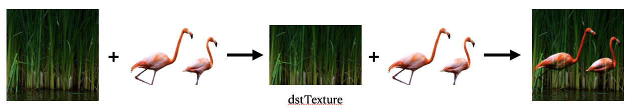
当然我们不需要把完整的 frame buffer 内容复制一份,因为我们的绘制区域可能只是局部。

复制局部 frame buffer 内容到纹理上,我们使用的是glCopyTexSubImage2D。这里还有一些其他的方式,比如glBlitFramebuffer,用这个的话,需要多创建一个 frame buffer,没有前一个方便和高效。

如果当前 frame buffer 已经绑定了一个纹理,而且当前的 OpenGL 也支持 glTextureBarrier,可以直接把这个绑定的纹理传入 shader,不过在绘制之前要调用一下glTextureBarrier

shader 公式

skia 的 shader 公式来源是 w3c - Advanced compositing features 的文档。

注意:公式里的 RGB 是 Premultiplied 还是 Unpremultiplied。

D2D 也有一份 blend 公式。这两份基本是一样的,w3c 的更全一点。

总结

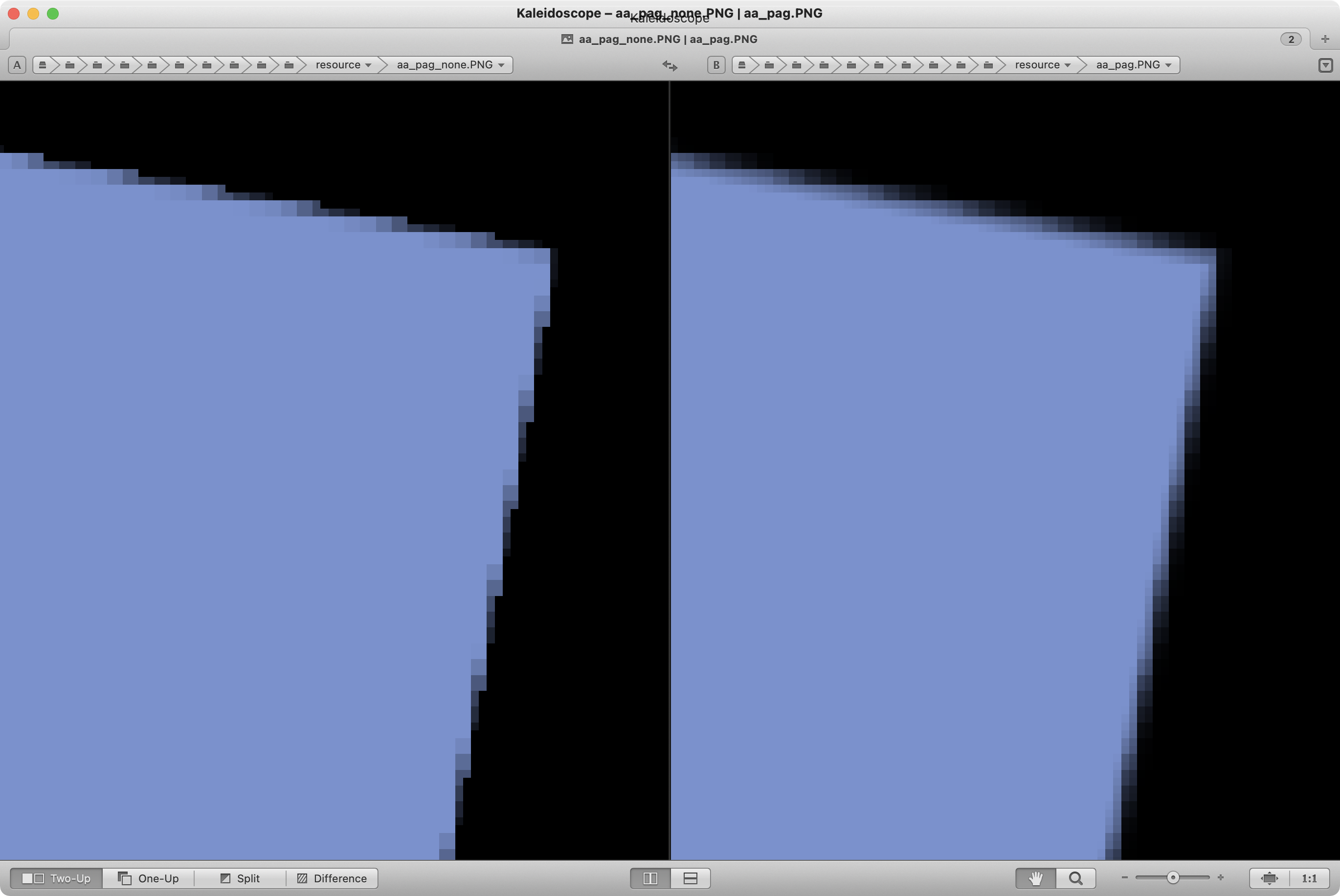
实现混合模式的整个过程,主要就是用 shader 实现的那部分比较复杂,因为需要考虑 OpenGL 的兼容性。

链接

skia
best method to copy texture to texture
OpenGL Reading from a texture unit currently bound to a framebuffer
SkBlendMode Overview
w3c - Advanced compositing features
D2D - blend

PAG 去掉 Skia 后如何渲染 Path

| Comments

问题

在 2D 绘图库中,path 绘制是很重要的一块。

思路

当我们要实现这一块的时候,优先想到的方案是封装一层接口,然后用平台侧的 API 去实现 path 的编辑和绘制,我们再提交到 OpenGL 去上屏。

但是经过调研发现,iOS 和 Mac 的 CGPath、web 的 Path2D 都没有实现类似 skia 的 path-ops 功能;Android 因为背后就是 skia,所以它的 API 和 skia 基本保持一致;在 linux 平台,没有找到合适的 path 编辑库。

然后发现 skia 有一个 module 叫 PathKit,可以把 skia 的 Path 编辑部分编译成 wasm 提供给 web 使用,渲染时把 SkPath 转成 Path2D 或者直接调用 web-canvas 的 path 接口。因为之前看过 rlottie 使用 freetype 来渲染 path,所以如果 SkPath 能转成 FTOutline,那么全平台的 path 渲染都可以用 freetype 来实现。

调研之后得出结论是 OK 的。

因为 freetype 会增加包大小,而且在 iOS 和 web 平台,用 freetype 没法使用系统字体,所以我们决定 path 编辑部分都使用 SkPath,渲染部分 iOS 和 Mac 用 CoreGraphics,web 平台使用 canvas,其他平台因为文字解析需要使用 freetype,就统一用 freetype 来渲染 path。

平台 path 渲染
iOS & Mac CoreGraphics
Android freetype
linux freetype
windows freetype
web canvas

在把 SkPath 转成 FT_Outline 时,要注意 FT_Outlinen_contoursn_pointsshort 类型,所以一个 SkPath 可能会转成多个 FT_Outline

pathkit

提取出来的代码我们作为第三方库 pathkit 来引入。

GPU 加速

skia 的 path 绘制有一部分是使用 GPU 加速的,而我们实现的是 CPU 绘制再提交到 GPU。

我们去调研了一下,这么多年以来,path 的绘制都是依赖 CPU 去实现的,GPU 在发展的过程中并没有考虑这个问题。Khronos 有一个硬件加速矢量绘制的标准 API,叫 OpenVG ,但是没有普及起来。Nvidia 提供了 GPU Accelerated Path Rendering ,也没有普及起来。而且不是所有的 path 都适合用 GPU 加速。

所以我们现阶段的方案是简单图形比如矩形、椭圆、圆等等,用 GPU 加速,复杂 path 比较少用,实现起来也比较麻烦,可以后续参考 skia 再支持 GPU 渲染。

链接

skia
path-ops
PathKit
rlottie
CoreGraphics-CGPath
CoreGraphics-CGContext
web-Path2D
web-Canvas
GPU-Accelerated-Path-Rendering
GPU-accelerated Path Rendering (2012) [pdf]
why have hardware accelerated vector graphics not taken off

PAG 支持 Web 做了哪些事

| Comments

思路

PAG 是纯 C++ 的项目,所以我们可以尝试通过 WebAssembly 在浏览器中运行。

首先我们的目标是先跑通一个纯矢量的 PAG 文件。

1. 用 freetype 跑通矢量绘制

我们需要用 emscripten 把 PAG 打成 wasm,PAG 的依赖库有很多,比如 ffmpeg、libpng、libjpeg、libwebp、zlib、pathkit、freetype、opengl 等,要跑通纯矢量的绘制,我们需要一个 OpenGL ES 的环境,再链接 pathkit 和 freetype 这两个库,其他的可以先不管。

寻找 OpenGL ES 的过程绕了一些弯路,不过万幸找到 emscripten 提供了 OpenGL ES 的 API,背后是 webgl 的实现。

wasm 链接第三方库也是 .a 的后缀,不过要用emcamke来生成 makefile,它会带入 emscripten 的环境变量,再去 build 就可以得到 wasm 支持的 .a。

把这两个库编译完,还需要一个 binding 文件来桥接 js 和 c++ 的代码,最后用emcc把 libpag.a、pathkit.a、freetype.a、binding.cpp 链接在一起生成 wasm 文件。

2. 视频序列帧

PAG 在其他平台是通过解码器来解码视频,web 平台不提供视频解码器,所以我们把 PAG 里面的裸 h264 流封装成 mp4 再放到 video 标签中播放,通过 seek 来控制进度,通过 txtImage2D来上传HTMLVideoElement的内容。

HTMLVideoElement 的 seek 是真的 seek,它没有做任何优化,所以当时间在一个 GOP 结尾的时候,HTMLVideoElement 的 seek 耗时非常久。因为 web 端的 PAG 只用于播放,不发生导出,所以这里画面没有对上也没关系,我们采用让它 play 起来,当下次请求时判断它当前的时间和我们请求的时间是否超过一个阈值,没有超过就不发生 seek;当有一段时间没有发生请求,就会自动暂停。

3. 图片解码

web 端对包大小很敏感,所以要尽量减少第三方库的依赖,像 png、jpg 的解码,web 的 image 标签就可以做到,然后通过txtImage2D上传到纹理,而 webp 因为平台的原因,浏览器不一定支持,这个库就不能去掉。

4. 文字

一开始我们用 freetype 来适配 web 端的文字渲染,搞完之后发现,web 没法提供系统字体的路径,如果用 freetype 来处理字体,需要在服务器上配置字体文件,web 端去下载注册到 freetype 中,而中文字体文件一般比较大,macOS 的苹方字体有 100M+,显然用户体验不会很好。我们去查了 flutter-web 的实现,它用的是 skia 的 web 版本,叫 CanvasKit,他们也是先下载字体然后注册之后使用。 我们调研了一下,可以用 web-font 来加载系统字体,用 web-canvas 来渲染,path 也可以用 web-canvas 渲染,这样 freetype 依赖就可以去掉,包又小了一点。

5. 包大小

做完以上这些,PAG 适配 web 端基本完成了,测试了一下包大小

size gzip
CanvasKit 6.6M 2.7M
pag 2.2M 643K

6. 性能

上面的弄完之后,发现每帧耗时都比较高,要 30ms+,通过浏览器的 Performance 工具发现是 OpenGL 调用耗时比较高,查看了 emscripten 的文章 Optimizing WebGL,按照上面的建议逐个排查,去掉 glGet*glGetErrorglCheckFramebufferStatus之后,每帧耗时明显降低。

7. PixiJS

之前的封装是基于 canvas 的,从 web 的 canvas 中创建webgl的 context,然后 PAG 在这个 context 中渲染。但是业务方是 web 端的视频编辑场景,可能加载很多个 PAG,webgl context 超出了浏览器的上限。

因为业务方使用的 PixiJS 本身就有一个 context,所以我们想直接共用一个 context,不再重新创建。

通过调查,PIXI.Resource可以做到这件事,在回调方法upload中,PixiJS 会传入PIXI.RendererPIXI.GLTexture,通过PIXI.Renderer我们可以拿到 webgl 的 context,通过PIXI.GLTexture我们可以拿到 webgl 的 texture,我们再把 context 和 texture 注册到 emscripten 的 GL 中,再用注册后的 texture 去创建 PAGSurface,就可以完成渲染。

这里要注意的是,upload传进来的 texture 可能会发生改变,所以在发现 texture 改变的时候,要从 emscripten 的 GL 中解注册,重新注册一个新的 texture,再创建一个新的 PAGSurface 去渲染。

调整进度接口直接写在这个PIXI.Resource的子类里面,再调用一下update方法,等 PixiJS 回调upload

示例代码如下

1
2
3
4
5
6
7
8
9
10
11
12
13
14
15
16
17
18
19
20
21
22
23
24
25
26
27
28
29
30
31
32
33
34
35
36
37
38
39
40
41
42
43
44
45
46
47
48
49
50
51
52
53
54
55
56
57
58
59
60
61
62
63
64
65
66
67
68
69
70
71
72
73
74
import { Resource } from 'pixi.js';

class PAGResource extends Resource {
  static async create(PAG, pagFile) {
    const width = await pagFile.width();
    const height = await pagFile.height();
    const pagResource = new PAGResource(width, height);
    pagResource.pagPlayer = await PAG.PAGPlayer.create();
    await pagResource.pagPlayer.setComposition(pagFile);
    pagResource.module = PAG;
    return pagResource;
  }

  private module;
  private contextID = null;
  private textureID = null;
  private pagPlayer = null;
  private pagSurface = null;

  constructor(width, height) {
    super(width, height);
  }

  async upload(renderer, baseTexture, glTexture) {
    const { width } = this;
    const { height } = this;
    glTexture.width = width;
    glTexture.height = height;

    const { gl } = renderer;

    // 注册 context  
    if (this.contextID === null) {
      this.contextID = this.module.GL.registerContext(gl, { majorVersion: 2, minorVersion: 0 });
    }

    if (glTexture.texture.name !== this.textureID) {
      // texture 变化  
      if (this.textureID !== null) {
        // 销毁旧的 surface  
        this.module.GL.textures[this.textureID] = null;
        this.pagSurface.destroy();
      }
      // 分配内存不然绑定 frameBuffer 会失败  
    gl.texImage2D(
        baseTexture.target,
        0,
        baseTexture.format,
        width,
        height,
        0,
        baseTexture.format,
        baseTexture.type,
        null,
      );
      // 注册  
      this.textureID = this.module.GL.getNewId(this.module.GL.textures);
      glTexture.texture.name = this.textureID;
      this.module.GL.textures[this.textureID] = glTexture.texture;
      // 生成 surface  
      this.module.GL.makeContextCurrent(this.contextID);
      this.pagSurface = await this.module._PAGSurface.FromTexture(this.textureID, width, height, false);
      await this.pagPlayer.setSurface(this.pagSurface);
    }
    await this.pagPlayer.flush();
    renderer.reset();
    return true;
  }

  public async setProgress(progress) {
    await this.pagPlayer.setProgress(progress);
    this.update();
  }
}

链接

WebAssembly
emscripten
PixiJS

OpenGL 绘制抗锯齿的圆角矩形

| Comments

思路

把圆角矩形分成 9 份,分别是 4 个角(p0p1p5p4、p2p3p7p6、p8p9p13p12、p10p11p15p14),4 个边缘(p1p2p6p5、p4p5p9p8、p6p7p11p10、p9p10p14p13)和 1 个中心(p5p6p10p11)。角的部分画弧,边缘和中心画矩形。

圆角矩形.png

顶点的定义除了常规的屏幕坐标,再提供一个小矩形的坐标,小矩形坐标的作用是计算点到图形轮廓的距离。

传进去的小矩形坐标经过标准化之后,不管是椭圆弧还是圆弧,都转化为半径为 1 的圆弧,根据公式 d = $\sqrt{x^2+y^2}$ - 1 可以计算距离。

中心矩形的小矩形坐标 x, y 都是 0;边缘四个矩形的小矩形坐标要么 x 是 0,要么 y 是 0,所以它计算的是点到边缘直线的距离。角上四个矩形的小矩形坐标计算的是点到圆弧的距离。

点到轮廓的距离为正,在图形外,alpha 为 0;为负在图形内,为 0 在图形上,alpha 为 1。

实现抗锯齿时,整个图形的坐标数据扩大 0.5px,用于 coverage 的计算。coverage 的范围是图形轮廓内外各 0.5px,加起来是 1px,也就是点到轮廓的距离[-0.5px, 0.5px],对应的 alpha 值为[0, 1]。

如果是圆弧的时候,上面的实现没问题,抗锯齿也完成的很好;但是如果是椭圆弧的时候,上面的实现就会出现下面的现象。比如按照比例缩小椭圆 80%,短半径从 5 到 4,长半径从 10 到 8,就是那个实线-内椭圆,和实线-外椭圆相比,它们之间的距离不是均匀的,而我们想要的是距离均匀的椭圆,也就是虚线的椭圆。

圆等距线拉伸成椭圆.png

所以上面的公式不适合用在椭圆上。

通过 skia 分享的 ppt,我们知道有一个公式可以计算点到椭圆的近似距离。

这个公式一般用来检测椭圆,也就是通过一些离散的点来拟合椭圆。

$d \approx \frac{f(x, y)}{|\nabla f(x, y)|}$ —> $d \approx \frac{\frac{x^2}{a^2}+\frac{y^2}{b^2}-1}{\sqrt{(\frac{2x}{a^2})^2+(\frac{2y}{b^2})^2}}$

可以从下面的链接找到这个公式的证明: Fitting conic sections to “very scattered” data: An iterative refinement of the Bookstein algorithm

vertex shader

1
2
3
4
5
6
attribute vec2 inPosition; // 屏幕坐标
attribute vec2 inEllipseOffset; // 小矩形坐标
attribute vec2 inEllipseRadii; // 椭圆 1/a, 1/b

varying vec2 vEllipseOffsets_Stage0 = inEllipseOffset;
varying vec2 vEllipseRadii_Stage0 = inEllipseRadii;

fragment shader

1
2
3
4
5
6
7
vec2 offset = vEllipseOffsets_Stage0*vEllipseRadii_Stage0;
float test = dot(offset, offset) - 1.0;
vec2 grad = 2.0*offset*vEllipseRadii_Stage0;
float grad_dot = dot(grad, grad);
grad_dot = max(grad_dot, 1.1755e-38);
float invlen = inversesqrt(grad_dot);
float edgeAlpha = clamp(0.5-test*invlen, 0.0, 1.0);

顶点的 index 数据,18 个三角形

1
2
3
4
5
6
7
8
9
10
11
12
13
14
// corners  
0, 1, 5, 0, 5, 4,
2, 3, 7, 2, 7, 6,
8, 9, 13, 8, 13, 12,
10, 11, 15, 10, 15, 14,

// edges  
1, 2, 6, 1, 6, 5,
4, 5, 9, 4, 9, 8,
6, 7, 11, 6, 11, 10,
9, 10, 14, 9, 14, 13,

// center  
5, 6, 10, 5, 10, 9,

上面说的是画一个填充的圆角矩形,还可以画一个 stroke 的圆角矩形,有兴趣可以看下 skia 的GrOvalFactory.cpp

链接

skia
DrawingAntialiasedEllipse
Sampson, P.D.: Fitting conic sections to “very scattered” data: An iterative refinement of the Bookstein algorithm. Comput. Graphics Image Process. 18, 97-108
Evaluating Harker and O’Leary’s Distance Approximation for Ellipse Fitting

纹理边缘抗锯齿 CoverageAA

| Comments

问题

用 OpenGL 旋转图片的时候,图片边缘会出现锯齿。

图 1 是没有做抗锯齿的时候,可以明显看到边缘的锯齿。


图 1

思路

首先想到的是 OpenGL 提供的 MSAA,但是 MSAA 占用内存比较多。然后去查了下 skia 的抗锯齿是如何实现的,发现它只是对图片边缘的 1px 做一个 alpha 从 1->0 渐变的遮罩。

如图 2 所示,矩形 abcd 是我们要绘制的区域,根据矩形的坐标向内缩 0.5px 得到矩形 P0_P1_P3_P2,向外扩 0.5px 得到矩形 P4_P5_P7_P6。内矩形里面 alpha 都是 1,外矩形边缘 alpha 都是 0,内矩形和外矩形之间 alpha 从 1->0 渐变。这样我们就对边缘做了一个逐渐消失的效果,从视觉上看,边缘的锯齿就没那么明显了。


图 2

解决

没有抗锯齿

在没有使用抗锯齿时,我们绘制一个矩形,提交的是 cdba 4 个顶点,2 个三角形。

1
2
3
4
5
6
7
8
auto bounds = args.rectToDraw;
auto normalBounds = Rect::MakeLTRB(0, 0, 1, 1);
return {
  bounds.right, bounds.bottom, normalBounds.right, normalBounds.bottom,
  bounds.right, bounds.top, normalBounds.right, normalBounds.top,
  bounds.left, bounds.bottom, normalBounds.left, normalBounds.bottom,
  bounds.left, bounds.top, normalBounds.left, normalBounds.top,
};

对应的绘制命令是

1
gl->drawArrays(GL_TRIANGLE_STRIP, 0, 4);

抗锯齿 CoverageAA

在使用 CoverageAA 抗锯齿时,我们绘制一个矩形,提交的是内矩形 P0P1P2P3 和外矩形 P4P5P6P7 的 8 个顶点:

1
2
3
4
5
6
7
8
9
10
11
12
13
14
15
16
17
18
19
20
auto bounds = args.rectToDraw;
auto normalBounds = Rect::MakeLTRB(0, 0, 1, 1);

auto padding = 0.5f;
auto insetBounds = bounds.makeInset(padding, padding);
auto outsetBounds = bounds.makeOutset(padding, padding);

auto normalPadding = Point::Make(padding / bounds.width(), padding / bounds.height());
auto normalInset = normalBounds.makeInset(normalPadding.x, normalPadding.y);
auto normalOutset = normalBounds.makeOutset(normalPadding.x, normalPadding.y);
return {
  insetBounds.left, insetBounds.top, 1.0f, normalInset.left, normalInset.top,
  insetBounds.left, insetBounds.bottom, 1.0f, normalInset.left, normalInset.bottom,
  insetBounds.right, insetBounds.top, 1.0f, normalInset.right, normalInset.top,
  insetBounds.right, insetBounds.bottom, 1.0f, normalInset.right, normalInset.bottom,
  outsetBounds.left, outsetBounds.top, 0.0f, normalOutset.left, normalOutset.top,
  outsetBounds.left, outsetBounds.bottom, 0.0f, normalOutset.left, normalOutset.bottom,
  outsetBounds.right, outsetBounds.top, 0.0f, normalOutset.right, normalOutset.top,
  outsetBounds.right, outsetBounds.bottom, 0.0f, normalOutset.right, normalOutset.bottom,
};

转换成三角形是 30 个顶点,下面是三角形的 index 数据

1
2
3
4
5
6
7
8
static constexpr int kIndicesPerAAFillRect = 30;
static constexpr uint16_t gFillAARectIdx[] = {
  0, 1, 2, 1, 3, 2,
  0, 4, 1, 4, 5, 1,
  0, 6, 4, 0, 2, 6,
  2, 3, 6, 3, 7, 6,
  1, 5, 3, 3, 5, 7,
};

绘制命令是

1
glDrawElements(GL_TRIANGLES, kIndicesPerAAFillRect, GL_UNSIGNED_SHORT, 0);

结果

图 3 是做完抗锯齿的效果,可以看到边缘的锯齿已经没有了。


图 3

图 4 是图 1 和 图 3 边缘对比的细节,可以看到边缘像素的过渡圆滑了很多。


图 4

链接

skia

纹理局部采样

| Comments

现象

在使用 MediaCodec 解码视频获取到纹理时,它会给出一个 cropRect 来裁剪多余的绿色像素。当拿着这个纹理和对应的 cropRect 去上屏的时候,发现在边缘的地方有一像素绿边。

如图所示,解码出的纹理大小是 1920*1088,有 8 像素的绿边;裁剪后大小是 1920*1080,有 1 像素绿边。

解码图片

裁剪后

纹素和像素的映射关系

一开始怀疑是纹素和像素的坐标系不一致的问题,对纹理坐标减了 0.5,发现还是有绿边。然后还找到坐标系不一致的问题只存在于 D3D9,后续的 D3D10 修改了坐标系的对应关系,而且 OpenGL 的坐标系一直没这个问题。

收缩 0.5 纹素

OpenGL ES Texture Coordinates Slightly Off上看到说只有当采样的点在纹素中心,才返回准确的颜色,否则就是插值出来的。也就是当采样的点在纹素中心和边界之间时,可能就会采到超出边界的颜色。

查 Android 源码

同时也发现使用SurfaceTexture.getTransformMatrix得到的 matrix 时,画面是正常的,所以去查看了 Android 的源码,想知道这个 matrix 是怎么生成的。

生成的逻辑就是下面这段代码,可以看到注释说为了防止双线性采样超过裁剪边缘,普通纹理需要收缩 0.5 纹素,YUV420的要收缩 1.0 纹素。

1
2
3
4
5
6
7
8
9
10
11
12
13
14
15
16
17
18
19
20
21
22
23
24
25
26
27
28
29
30
31
32
33
34
35
36
37
38
39
40
41
42
43
44
45
46
47
48
49
50
51
52
53
54
55
56
......
......
void SurfaceTexture::computeTransformMatrix(float outTransform[16], const sp<GraphicBuffer>& buf,
                                            const Rect& cropRect, uint32_t transform,
                                            bool filtering) {
  ......
    if (!cropRect.isEmpty() && buf.get()) {
        float tx = 0.0f, ty = 0.0f, sx = 1.0f, sy = 1.0f;
        float bufferWidth = buf->getWidth();
        float bufferHeight = buf->getHeight();
        float shrinkAmount = 0.0f;
        if (filtering) {
            // In order to prevent bilinear sampling beyond the edge of the
            // crop rectangle we may need to shrink it by 2 texels in each
            // dimension.  Normally this would just need to take 1/2 a texel
            // off each end, but because the chroma channels of YUV420 images
            // are subsampled we may need to shrink the crop region by a whole
            // texel on each side.
            switch (buf->getPixelFormat()) {
                case PIXEL_FORMAT_RGBA_8888:
                case PIXEL_FORMAT_RGBX_8888:
                case PIXEL_FORMAT_RGBA_FP16:
                case PIXEL_FORMAT_RGBA_1010102:
                case PIXEL_FORMAT_RGB_888:
                case PIXEL_FORMAT_RGB_565:
                case PIXEL_FORMAT_BGRA_8888:
                    // We know there's no subsampling of any channels, so we
                    // only need to shrink by a half a pixel.
                    shrinkAmount = 0.5;
                    break;

                default:
                    // If we don't recognize the format, we must assume the
                    // worst case (that we care about), which is YUV420.
                    shrinkAmount = 1.0;
                    break;
            }
        }

        // Only shrink the dimensions that are not the size of the buffer.
        if (cropRect.width() < bufferWidth) {
            tx = (float(cropRect.left) + shrinkAmount) / bufferWidth;
            sx = (float(cropRect.width()) - (2.0f * shrinkAmount)) / bufferWidth;
        }
        if (cropRect.height() < bufferHeight) {
            ty = (float(bufferHeight - cropRect.bottom) + shrinkAmount) / bufferHeight;
            sy = (float(cropRect.height()) - (2.0f * shrinkAmount)) / bufferHeight;
        }

        mat4 crop(sx, 0, 0, 0, 0, sy, 0, 0, 0, 0, 1, 0, tx, ty, 0, 1);
        xform = crop * xform;
    }
  ......
}
......
......

再看一遍SurfaceTexture.getTransformMatrix)发现也有说明。

双线性插值(Bilinear Filtering)

双线性插值会取临近 4 个像素的加权平均值。

bilinear_filtering.jpg

上面的情况我们在传递的是图片边缘的 UV 坐标,那么由于双线性采样,它就会采到下面绿色的像素;如果我们传递的 UV 坐标收缩 0.5px,那么边缘外面的像素权重会是 0,就采不到绿色。

链接

OpenGL ES Texture Coordinates Slightly Off
SurfaceTexture::computeTransformMatrix
SurfaceTexture.getTransformMatrix)
图形学底层探秘 - 纹理采样、环绕、过滤与Mipmap的那些事
Directly Mapping Texels to Pixels (Direct3D 9)

Mp3精准seek与比特池技术

| Comments

ffmpeg 的 seek flag AVSEEK_FLAG_ANY 并不精准。

起因

最近在做音频剪辑的功能,有下面的场景

一段音频,一个时间区间将它分成三段,前段和后段速度保持不变,中间一段变速2倍。

实现上,我分成了三个不同的 segment 来处理,segment.start 不等于 0 的,会执行一下 seek,使用的是 ffmpeg 的 AVSEEK_FLAG_ANY | AVSEEK_FLAG_BACKWARD,来精准 seek,完成之后发现段与段交接的地方声音并不连贯。

剪映

研究了竞品,发现也有这个问题,剪映编辑音乐录屏
分析了一下视频的波形,可以看到在 11s 的位置有缝。

裁剪 frame

我已经做了一个处理,在段结尾的时候,裁掉多余的bytes,在段开始的时候也裁掉,保证段与段之间解码后的数据连续。但是声音还是不连续。

1
2
3
4
5
6
7
8
9
10
11
12
13
14
15
16
17
18
19
20
21
22
23
24
25
26
27
std::shared_ptr<SampleData> AudioSegmentReader::copyNextSample() {
    if (currentLength >= endLength) {
        return nullptr;
    }
    auto data = copyNextSampleInternal();
    if (data == nullptr) {
        return nullptr;
    }
    // 裁掉结尾多余的 bytes
    data->length = std::min(data->length, endLength -   currentLength);
    currentLength += data->length;
    return data;
}

// 解码出的数据判断是否需要裁掉开头的 bytes
data = decoder->onRenderFrame();
auto time = decoder->currentPresentationTime();
if (0 <= time && time < startTime) {
    auto delta = startLength - SampleTimeToLength(time, outputSetting.get());
    if (delta < data->length) {
        data->data += delta;
        data->length -= delta;
    } else {
        data->data = nullptr;
        data->length = 0;
    }
}

排查 packet 和 frame

打印了一下段与段连接地方的 packet 的 packetData 和 frameData,发现 packetData 正常,seek 之后的 frameData 中前面大部分是 0,和上一段结尾解出的 frameData 不一样。记得音频帧可以独立解码,不需要参考前面的帧数据,那问题出现在哪里?

一个测试:解封装连续,解码之前 flush 一下 decoder,会发现 frameData 前面都有0,和不 flush decoder 的情况不一样。

了解 mp3 帧头格式

很多规则,但是没卵用。

比特池技术(bit reservoir)

最后去查 mp3 的解码过程实现,发现 mp3 使用了比特池技术,当前帧的主数据可能放在上一帧。。。。也就是要实现精准 seek,得往前多 seek 几帧,然后把前面的 frame 丢掉。 试了一下,结果如预期。

结尾

最后放一个修复前后的波形对比图。 第一条波形是一个 Segment 时候的波形; 第二条是从中间剪开,两个 Segment 的波形,会发现中间有缝; 第三条是修复后的波形。

参考

mp3比特池技术
功耗高集成度MP3解码器IP核设计
维基百科-MP3
维基百科-AAC

如何获取VideoToolbox的reorder Size

| Comments

Decoder 的区别

FFmpeg 和 MediaCodec 解码的时候,送数据的顺序是 dts,出数据的顺序是 pts,而 VideoToolbox 是送一个出一个,没有按照 pts 来出数据,需要我们自己排序。

去网上查资料的时候,发现有很多不同的方式

  1. sps.max_num_ref_frames
  2. sps.vui.max_num_reorder_frames
  3. 通过 sps.level 计算
  4. 直接设置为4

通过测试几个文件的 sps 发现 max_num_ref_frames 不是很准

  1. max_num_ref_frames=0; max_num_reorder_frames=2
  2. max_num_ref_frames=9; max_num_reorder_frames=2

sps.max_num_ref_frames

max_num_ref_frames 的有两个播放器,ijkplayer 和 ThumbPlayer

ijkplayer

ijkplayer 的逻辑是先取 sps.max_num_ref_frames,然后再取最小值2,最大值5。

1
2
3
fmt_desc->max_ref_frames = FFMAX(fmt_desc->max_ref_frames, 2);

fmt_desc->max_ref_frames = FFMIN(fmt_desc->max_ref_frames, 5);

主要代码在下面两个文件。
IJKVideoToolBoxAsync.m
h264_sps_parser.h

ThumbPlayer

ThumbPlayer 的逻辑是取 sps.max_num_ref_frames,如果没有设置为 10。

sps.vui.max_num_reorder_frames

max_num_reorder_frames 的有三个

  1. Chrome
  2. vlc
  3. MediaCodec

Chrome

Chrome 的主要代码如下,代码文件在vt_video_decode_accelerator_mac.cc

  1. 先判断 pocType,为 2 直接返回不需要排序
  2. 再判断是否有 vuiParameters,取 max_num_reorder_frames
  3. 然后是特定的 profile,不需要排序
  4. 最后返回 max_dpb_frames 的 默认值16
1
2
3
4
5
6
7
8
9
10
11
12
13
14
15
16
17
18
19
20
21
22
23
int32_t ComputeReorderWindow(const H264SPS* sps) {
  // When |pic_order_cnt_type| == 2, decode order always matches presentation
  // order.
  // TODO(sandersd): For |pic_order_cnt_type| == 1, analyze the delta cycle to
  // find the minimum required reorder window.
  if (sps->pic_order_cnt_type == 2)
    return 0;

  // TODO(sandersd): Compute MaxDpbFrames.
  int32_t max_dpb_frames = 16;

  // See AVC spec section E.2.1 definition of |max_num_reorder_frames|.
  if (sps->vui_parameters_present_flag && sps->bitstream_restriction_flag) {
    return std::min(sps->max_num_reorder_frames, max_dpb_frames);
  } else if (sps->constraint_set3_flag) {
    if (sps->profile_idc == 44 || sps->profile_idc == 86 ||
        sps->profile_idc == 100 || sps->profile_idc == 110 ||
        sps->profile_idc == 122 || sps->profile_idc == 244) {
      return 0;
    }
  }
  return max_dpb_frames;
}

vlc

vlc 的逻辑和 chrome 类似,多了一个根据 level 计算 max_dpb_frames

  1. 判断是否有 vuiParameters,取 max_num_reorder_frames
  2. 然后是特定的 profile,不需要排序
  3. 最后计算 max_dpb_frames

代码文件在h264_nal.c

1
2
3
4
5
6
7
8
9
10
11
12
13
14
15
16
17
18
19
20
21
22
23
24
25
26
27
28
29
30
31
32
33
34
35
36
37
38
39
40
41
42
43
44
45
46
47
48
49
static uint8_t h264_get_max_dpb_frames( const h264_sequence_parameter_set_t *p_sps )
{
    const h264_level_limits_t *limits = h264_get_level_limits( p_sps );
    if( limits )
    {
        unsigned i_frame_height_in_mbs = ( p_sps->pic_height_in_map_units_minus1 + 1 ) *
                                         ( 2 - p_sps->frame_mbs_only_flag );
        unsigned i_den = ( p_sps->pic_width_in_mbs_minus1 + 1 ) * i_frame_height_in_mbs;
        uint8_t i_max_dpb_frames = limits->i_max_dpb_mbs / i_den;
        if( i_max_dpb_frames < 16 )
            return i_max_dpb_frames;
    }
    return 16;
}

bool h264_get_dpb_values( const h264_sequence_parameter_set_t *p_sps,
                          uint8_t *pi_depth, unsigned *pi_delay )
{
    uint8_t i_max_num_reorder_frames = p_sps->vui.i_max_num_reorder_frames;
    if( !p_sps->vui.b_bitstream_restriction_flag )
    {
        switch( p_sps->i_profile ) /* E-2.1 */
        {
            case PROFILE_H264_BASELINE:
                i_max_num_reorder_frames = 0; /* only I & P */
                break;
            case PROFILE_H264_CAVLC_INTRA:
            case PROFILE_H264_SVC_HIGH:
            case PROFILE_H264_HIGH:
            case PROFILE_H264_HIGH_10:
            case PROFILE_H264_HIGH_422:
            case PROFILE_H264_HIGH_444_PREDICTIVE:
                if( p_sps->i_constraint_set_flags & H264_CONSTRAINT_SET_FLAG(3) )
                {
                    i_max_num_reorder_frames = 0; /* all IDR */
                    break;
                }
                /* fallthrough */
            default:
                i_max_num_reorder_frames = h264_get_max_dpb_frames( p_sps );
                break;
        }
    }

    *pi_depth = i_max_num_reorder_frames;
    *pi_delay = 0;

    return true;
}

MediaCodec

MediaCodecvlc/Chrome也差不多,计算max_dpb_frames的时候考虑了max_num_ref_framesmax_dec_frame_buffering

1
2
3
4
5
6
7
8
9
10
11
12
13
14
15
16
17
18
19
20
21
22
23
24
25
26
27
28
29
30
31
32
33
34
35
36
37
38
39
40
41
42
43
44
45
46
47
48
49
50
51
52
53
54
55
56
57
58
59
60
61
62
63
64
65
66
67
68
69
70
71
72
73
74
75
76
77
78
79
80
81
82
83
84
85
86
87
88
89
90
91
92
93
94
95
96
97
98
99
100
101
102
103
104
105
106
107
108
109
110
111
112
113
114
bool H264Decoder::ProcessSPS(int sps_id, bool* need_new_buffers) {
  DVLOG(4) << "Processing SPS id:" << sps_id;

  const H264SPS* sps = parser_.GetSPS(sps_id);
  if (!sps)
    return false;

  *need_new_buffers = false;

  if (sps->frame_mbs_only_flag == 0) {
    DVLOG(1) << "frame_mbs_only_flag != 1 not supported";
    return false;
  }

  Size new_pic_size = sps->GetCodedSize().value_or(Size());
  if (new_pic_size.IsEmpty()) {
    DVLOG(1) << "Invalid picture size";
    return false;
  }

  int width_mb = new_pic_size.width() / 16;
  int height_mb = new_pic_size.height() / 16;

  // Verify that the values are not too large before multiplying.
  if (std::numeric_limits<int>::max() / width_mb < height_mb) {
    DVLOG(1) << "Picture size is too big: " << new_pic_size.ToString();
    return false;
  }

  int level = sps->level_idc;
  int max_dpb_mbs = LevelToMaxDpbMbs(level);
  if (max_dpb_mbs == 0)
    return false;

  // MaxDpbFrames from level limits per spec.
  size_t max_dpb_frames = std::min(max_dpb_mbs / (width_mb * height_mb),
                                   static_cast<int>(H264DPB::kDPBMaxSize));
  DVLOG(1) << "MaxDpbFrames: " << max_dpb_frames
           << ", max_num_ref_frames: " << sps->max_num_ref_frames
           << ", max_dec_frame_buffering: " << sps->max_dec_frame_buffering;

  // Set DPB size to at least the level limit, or what the stream requires.
  size_t max_dpb_size =
      std::max(static_cast<int>(max_dpb_frames),
               std::max(sps->max_num_ref_frames, sps->max_dec_frame_buffering));
  // Some non-conforming streams specify more frames are needed than the current
  // level limit. Allow this, but only up to the maximum number of reference
  // frames allowed per spec.
  DVLOG_IF(1, max_dpb_size > max_dpb_frames)
      << "Invalid stream, DPB size > MaxDpbFrames";
  if (max_dpb_size == 0 || max_dpb_size > H264DPB::kDPBMaxSize) {
    DVLOG(1) << "Invalid DPB size: " << max_dpb_size;
    return false;
  }

  if ((pic_size_ != new_pic_size) || (dpb_.max_num_pics() != max_dpb_size)) {
    if (!Flush())
      return false;
    DVLOG(1) << "Codec level: " << level << ", DPB size: " << max_dpb_size
             << ", Picture size: " << new_pic_size.ToString();
    *need_new_buffers = true;
    pic_size_ = new_pic_size;
    dpb_.set_max_num_pics(max_dpb_size);
  }

  Rect new_visible_rect = sps->GetVisibleRect().value_or(Rect());
  if (visible_rect_ != new_visible_rect) {
    DVLOG(2) << "New visible rect: " << new_visible_rect.ToString();
    visible_rect_ = new_visible_rect;
  }

  if (!UpdateMaxNumReorderFrames(sps))
    return false;
  DVLOG(1) << "max_num_reorder_frames: " << max_num_reorder_frames_;

  return true;
}

bool H264Decoder::UpdateMaxNumReorderFrames(const H264SPS* sps) {
  if (sps->vui_parameters_present_flag && sps->bitstream_restriction_flag) {
    max_num_reorder_frames_ =
        base::checked_cast<size_t>(sps->max_num_reorder_frames);
    if (max_num_reorder_frames_ > dpb_.max_num_pics()) {
      DVLOG(1)
          << "max_num_reorder_frames present, but larger than MaxDpbFrames ("
          << max_num_reorder_frames_ << " > " << dpb_.max_num_pics() << ")";
      max_num_reorder_frames_ = 0;
      return false;
    }
    return true;
  }

  // max_num_reorder_frames not present, infer from profile/constraints
  // (see VUI semantics in spec).
  if (sps->constraint_set3_flag) {
    switch (sps->profile_idc) {
      case 44:
      case 86:
      case 100:
      case 110:
      case 122:
      case 244:
        max_num_reorder_frames_ = 0;
        break;
      default:
        max_num_reorder_frames_ = dpb_.max_num_pics();
        break;
    }
  } else {
    max_num_reorder_frames_ = dpb_.max_num_pics();
  }

  return true;
}

sps.level 计算

vlcMediaCodec 都计算得出dpb.max_num_pics,拿这个值保底
gst-plugins-bad 只通过 level 计算,计算部分和 MediaCodec一样。

设置为4

iOS解码关于视频中带B帧排序问题

HEVC

vlc 中还有 HEVC(H265) 视频获取 max_num_reorder 的方式,代码文件在hevc_nal.c

FFmpeg

h264
h265

总结

  • ChromevlcMediaCodec的策略几乎一致,MediaCodec逻辑最完整。
  • vlc还处理了hevcmax_num_reorder

Link

ijkplayer
Chrome
vlc
Android
FFmpeg
iOS解码关于视频中带B帧排序问题

iOS NV12转SkImage颜色不正常的问题

| Comments

环境

设备:iPhone 6s
系统:13.1
Skia版本:m62
视频的YUV ColorSpace:ITU-R BT.601

现象

VideoToolbox 配置的 pixelFormat 是kCVPixelFormatType_420YpCbCr8BiPlanarVideoRange,然后把输出的 pixelBuffer 用下面的代码片段1转成 NV12,再使用代码片段2转成 SkImage,在 SkCanvas 上 draw 出来如图1,视频原图如图2。

1
uint32_t pixelFormatType = kCVPixelFormatType_420YpCbCr8BiPlanarVideoRange;
1
2
3
4
5
6
7
8
9
10
11
12
13
14
15
16
17
18
19
20
21
22
23
24
25
26
27
// 代码片段1
// Y 数据
CVOpenGLESTextureCacheCreateTextureFromImage(kCFAllocatorDefault,
                                             textCache,
                                             pixelBuffer,
                                             NULL,
                                             GL_TEXTURE_2D,
                                             GL_LUMINANCE,
                                             width,
                                             height,
                                             GL_LUMINANCE,
                                             GL_UNSIGNED_BYTE,
                                             0,
                                             &outputTextureLuma);
// UV 数据
CVOpenGLESTextureCacheCreateTextureFromImage(kCFAllocatorDefault,
                                             textCache,
                                             pixelBuffer,
                                             NULL,
                                             GL_TEXTURE_2D,
                                             GL_LUMINANCE_ALPHA,
                                             width / 2,
                                             height / 2,
                                             GL_LUMINANCE_ALPHA,
                                             GL_UNSIGNED_BYTE,
                                             1,
                                             &outputTextureChroma);
1
2
3
4
5
6
7
8
9
10
11
12
13
// 代码片段2
GrGLTextureInfo textureInfo1 = {videoImage->textureTarget(), videoImage->getTextureID(0)};
GrGLTextureInfo textureInfo2 = {videoImage->textureTarget(), videoImage->getTextureID(1)};
GrBackendObject nv12TextureHandles[] = {reinterpret_cast<GrBackendObject>(&textureInfo1),
                                        reinterpret_cast<GrBackendObject>(&textureInfo2)};
SkISize nv12Sizes[] = \{\{videoImage->width(), videoImage->height()\},
                       \{videoImage->width(), videoImage->height()\}\};
skImage = SkImage::MakeFromNV12TexturesCopy(grContext,
                                            kRec601_SkYUVColorSpace,
                                            nv12TextureHandles,
                                            nv12Sizes,
                                            kTopLeft_GrSurfaceOrigin,
                                            nullptr);

图1 图2

查问题

1. 查视频的 YUV ColorSpace 是否和 SkImage 对应

是一致的,但输出的图像还是有问题。

2.试试把 VideoToolbox 的输出格式换成 RGBA

配置 VideoToolbox 的 pixelFormat 为 kCVPixelFormatType_32BGRA,使用代码片段3把 pixelBuffer 转成 RGBA 纹理,然后使用代码片段4转成 SkImage,图像是正常的。

1
uint32_t pixelFormatType = kCVPixelFormatType_32BGRA;
1
2
3
4
5
6
7
8
9
10
11
12
13
// 代码片段3
CVOpenGLESTextureCacheCreateTextureFromImage(kCFAllocatorDefault,
                                             textCache,
                                             pixelBuffer,
                                             NULL,
                                             GL_TEXTURE_2D,
                                             GL_RGBA,
                                             width,
                                             height,
                                             GL_BGRA,
                                             GL_UNSIGNED_BYTE,
                                             0,
                                             &outputTextureLuma);
1
2
3
4
5
6
// 代码片段4
GrGLTextureInfo textureInfo = {videoImage->textureTarget(), videoImage->getTextureID(0)};
GrBackendTexture backendTexture(videoImage->width(), videoImage->height(), kRGBA_8888_GrPixelConfig,
                                textureInfo);
skImage =  SkImage::MakeFromTexture(grContext, backendTexture, kTopLeft_GrSurfaceOrigin,
                                    kPremul_SkAlphaType, nullptr);

3.查 Skia 源码

1
2
3
4
// SkImage_Gpu.cpp
// SkImage::MakeFromNV12TexturesCopy -> make_from_yuv_textures_copy
// GrYUVEffect.cpp
// GrYUVEffect::MakeYUVToRGB -> YUVtoRGBEffect::Make -> YUVtoRGBEffect() -> onCreateGLSLInstance() -> GLSLProcessor -> shader '.rg'

从 Skia 的源码中一直跟下去,发现最后 shader 使用的是 rg 通道,而因为我们是用 GL_LUMINANCE_ALPHA 来获取 UV 数据,在 GLSL 中应该使用 ra 通道,所以出现了不一致。当使用GL_RG获取UV数据的时候(代码片段5),SkImage 输出的图片就正常了。

1
2
3
4
5
6
7
8
9
10
11
12
13
14
// 代码片段5
// UV 数据
CVOpenGLESTextureCacheCreateTextureFromImage(kCFAllocatorDefault,
                                             textCache,
                                             pixelBuffer,
                                             NULL,
                                             GL_TEXTURE_2D,
                                             GL_RG,
                                             width / 2,
                                             height / 2,
                                             GL_RG,
                                             GL_UNSIGNED_BYTE,
                                             1,
                                             &outputTextureChroma);

Link

skia
GL 移植到 Metal 的小细节

App 多区域皮肤(主题)的实现

| Comments

需求

App 里可以皮肤化的 UI 区域分为 3 块(App 皮肤/阅读器主题/其他),这 3 块又和黑夜模式有重叠。

  • App 皮肤区域有首页 4 个 tab bar 页面(还没有实现主题化,在规划中)
  • 阅读器主题区域主要是阅读器相关的设置和菜单页面
  • 其他指不需要主题化的区域

第一种方案

主要思路就是给 UIKit 的 Category 增加一些属性,配置每一类主题的 key,在第一次赋值或者收到主题改变的通知时进行 apply。

qd 是黑夜模式前缀,readerTheme 是阅读器主题前缀

这种方案的问题是 - 如果要增加一类主题(比如 App 皮肤类),需要把所有之前增加的属性都 copy 一下(包括 apply 部分的代码),工作量很大。 - 如果要增加一个新的属性,需要添加多遍(前缀分别是qd/readerTheme/app)。

重构之后的方案

借助 OC 的泛型和 KVC 的一次重构

重构前后对比

代码实现样例:LVThemeKit